


PF maestro – APF-09Y Series
PF maestro – APF-09Y Series
PF meastro – APF-09Y Series is a Single CT smart Automatic Power Factor Correction (APFC) Controller built on advanced 32-bit ARM Cortex-M microcontroller technology with integrated Digital Signal Processing (DSP). It offers precise power measurements, real-time monitoring, and intelligent control of capacitor banks to improve power factor in industrial and commercial electrical systems.
Our Product Features
Advanced 32-bit ARM Cortex-M Microcontroller with DSP Logic
Incorporates a state-of-the-art 32-bit ARM Cortex-M processor with integrated Digital Signal Processing (DSP) capabilities. This enables high-speed, real-time data acquisition and processing for accurate measurement, monitoring, indication, alarming, and automated control of power factor correction functions.
Standards-Compliant Power Measurement
Accurately measures Active (P) and Reactive (Q) power in accordance with IEC 62053 Part 21 & 23, Class 3.0, ensuring reliable performance and compliance with international energy metering standards.
Auto CT Polarity Detection
Features automatic detection and indication of Current Transformer (CT) polarity, with user-editable settings to simplify installation and ensure measurement accuracy.
Dedicated Voltage Feedback Inputs
Provides Phase-to-Phase voltage measurement through independent input terminals, enhancing flexibility and precision in diverse installation setups.
Single CT Current Feedback Interface
Supports single CT-based current measurement through a three-terminal side connector located at the rear, allowing for simplified wiring while maintaining accuracy.
Harmonic Analysis Capability
Measures supply voltage and current, along with odd harmonic coefficients up to the 15th harmonic, helping users monitor and manage power quality effectively.
Wide Input Voltage Range Support
Capable of operating over a broad AC input voltage range, accommodating various system configurations and ensuring adaptability in diverse power environments.
Multiple Capacitor Switching Modes
Offers several capacitor bank switching to optimize power factor correction:
Un-equal Mode – User-defined step sizes for flexible compensation.
C-Series Mode – Predefined standard capacitor bank sequences
E-Series Mode – Custom-defined, energy-optimized sequences
Capacitor Bank Step Control
Supports control of 4, 6, 8, 10, or 12 output capacitor steps, depending on the selected unit model, allowing precise reactive power compensation tailored to load demand.
Auxiliary Digital Input & Output
Includes a 24V DC auxiliary digital input for external triggering or interlocks, and a potential- free Normally Open (N.O.) relay contact output. This output can be used for system interlocks or to control auxiliary equipment such as an APFC panel cooling fan (if enabled).
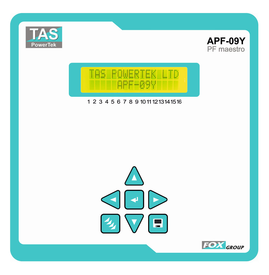
User-Friendly Display
Equipped with a 16-character x 2-line LCD display featuring LED backlighting, ensuring clear visibility of system status, measurements, and alerts even in low-light conditions.
Rugged and Standardized Enclosure
Housed in a DIN standard 144mm x 144mm panel-mountable enclosure, made from fire-retardant plastic, designed for secure and safe integration into electrical panels.
Comprehensive Built-in Protections
The unit includes user-configurable protections to safeguard system performance and longevity :
Over and under supply voltage
Overcurrent or under load (based on kW)
Over-temperature protection for the APFC unit
Capacitor bank step health monitoring
Technical Specifications
| Parameter | Specifications |
|---|---|
| Feed-back Voltage | 2-Ph., 2-wire (Phase-to-Phase), Nominal 415 Volts (User Settable Range: 100 to 480 Vac, in steps of 1 Volt) |
| Supply Current Feedback (CT) Input | Selectable 5 Amp or 1 Amp |
| Measurement Accuracy | Class 2 for Voltage & Current |
| Power Measurement Accuracy | Class 3 (P-Active & Q-Reactive) |
| Mains AC Supply Frequency Range | 47 Hz to 53 Hz (Nominal 50 Hz) or 57 Hz to 63 Hz (Nominal 60 Hz) |
| Power Factor Correction Cycle Time Range | User Selectable: 1 to 180 Seconds (in steps of 1 Second) |
| Capacitor Bank Discharge Time Range | User Selectable: 1 to 180 Seconds (in steps of 1 Second) |
| Output Commands | 4 / 6 / 8 / 10 / 12 Relay ‘NO’ Contacts (Isolated, 5 Amp Resistive / 0.5 Amp Inductive / 250 Vac) |
| Relay Contact Usage | Suitable for Three-Phase Capacitor-Duty Contactor Coils (Nominal <250 Vac, 50 Hz) |
| Current-Sourcing transistor contact | Max. 20 milli-Amp Current-Sourcing Transistor Outputs, using external supply of 12Vdc / 24Vdc, Current-Sourcing Transistor Outputs are Short-Circuit Protected |
| ENVIRONMENTAL | |
| Operating Temperature Range | -10°C to +60°C |
| Storage Temperature Range | -10°C to +65°C |
| STANDARDS COMPLIANCE | |
| EMC / EMI | IEC 62326 – 1 |
| Environment | IEC 60068 (Temp, Humid, Rust) IP-54 (front), IP-20A (back) |
| Measurement Accuracy – P & Q | IEC 62053 pt.21,23 table-6 Class-3.0 |
All specifications are typical and subject to change without notice due to ongoing product development and improvement.