


PF maestro-SPF-21X-Series
PF maestro-SPF-21X-Series
PF maestro – SPF-21X Seriesis a high-performance, intelligent power factor correction controller designed for modern industrial power systems. It offers real-time, automatic power factor correction with precision up to three decimal places, optimizing energy efficiency and voltage stability. With support for 8+1 capacitor step control, advanced four-quadrant energy metering,and robust communication via MODBUS, this product series enables seamless integration into SCADA and energy management systems. It features built-in harmonic monitoring, capacitor health diagnostics without extra sensors. Engineered for flexibility and durability, it supports wide voltage ranges, operates reliably in harsh environments, and ensures safe, efficient capacitor switching through programmable delays and interleaving. This series is the ideal solution for industrial and commercial users seeking reliable, scalable, and intelligent power factor correction.
Our Product Features
Real-time Automatic Displacement Power Factor (D-PF) Correction
SPF-21X intelligently switches capacitor banks to maintain a programmable target PF up to three decimal places, ensuring optimal energy efficiency, improved voltage stability, and reduced utility penalties across dynamic industrial loads.
8+1 Capacitor Bank Step Control with Auxiliary Output
Capable of managing eight capacitor banks plus one auxiliary output for either an additional capacitor or alarm/trip function, providing flexible system expansion without hardware redesign.
Four-Quadrant Energy Measurement with IEC-62053 Class 3.0 Compliance
Accurately measures Active, Reactive, Apparent, and Distortion Power, supporting complex import/export systems and enabling precise energy audits and billing verification.
Built-in RS-485 Communication Supporting MODBUS-RTU and MODBUS-ASCII
Allows real-time remote monitoring and full configuration from SCADA, BMS, or energy management systems, streamlining centralized control and diagnostics.
Wide Auxiliary Supply Range of 90-485V AC
The wide voltage range ensures the meter continues to function safely even during voltage fluctuations, preventing unexpected shutdowns or failures that could lead to electrical hazards,overheating, or damage to connected equipment.
Easy Edit Mode for Quick Setup and Expert Edit Mode for Advanced Programming
Enables fast commissioning for standard systems while providing deep customization options such as CT correction, vector adjustment, step mapping, and generator management for complex installations.
Automatic and Manual Current-Voltage Wiring Synchronization
Corrects CT polarity, phase sequencing, and vector configuration internally without requiring rewiring, reducing installation errors and commissioning time.
Dual Programmable Power Factor Targets for Grid and Generator Supply
Automatically adjusts PF targets based on detected supply type, protecting generators from leading PF damage and maintaining optimal network power factor during transitions.
Capacitor Step Utilization Tracking (Switching Count and ON-Time Monitoring)
Tracks each capacitor step's switching frequency and operating hours, calculates realistic usage levels, and enables predictive maintenance scheduling to prevent unplanned failures.
Capacitor Health Monitoring Without Additional Current Sensors
Analyzes VAR contribution per switching operation to detect faulty capacitors without needing extra CTs, saving installation costs while maintaining system integrity.
Programmable Step Usage Limits Based on Capacitor Duty Cycles
Configurable lifetime thresholds per capacitor step trigger timely maintenance alerts,optimizing asset lifespan and system reliability .
Capacitor Discharge Delay Control for Contact Protection
Applies programmable discharge delays between capacitor switching operations to ensure safe re-energization, protecting contactors from residual voltage damage and extending equipment life.
Interleaving Delay Between Capacitor Switching Events
Introduces adjustable delay between successive step activations, preventing simultaneous inrush surges and stabilizing network voltage levels.
Advanced Fault Monitoring with Over 47 Fault Types
Detects and responds to various system faults with programmable fault reaction strategies,ensuring full protection and uptime.
Internal Data Logging and Event Recording
Records energy usage, fault histories, and operational summaries, enabling data-driven preventive maintenance.
Harmonic Monitoring for Voltage and Current up to the 31st Order
Detects and helps mitigate harmonic-related power quality issues, protecting system components.
Fully Configurable Relay and Auxiliary Outputs
Supports custom assignment for alarms, fans, trips, and extended capacitor control, increasing system flexibility.
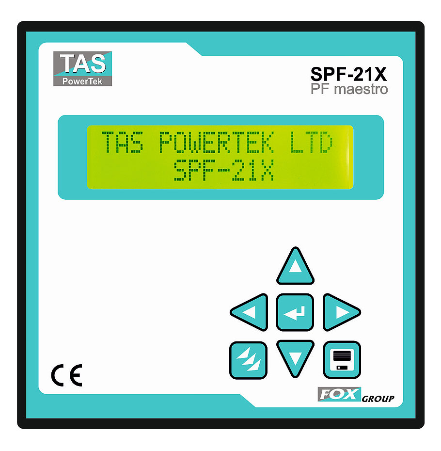
User-Friendly 2-Line LCD Display with 7-Key Navigation Keypad
Facilitates easy parameter viewing and device configuration even in poor lighting conditions.
Robust Industrial Build with IP54 Front Protection and Fire-Retardant ABS Housing
Ensures reliable, safe operation in harsh industrial environments.
Technical Specifications
| Function | Parameter | Condition | Minimum | Maximum |
|---|---|---|---|---|
| Measurement | ||||
| Supply | Voltage (V) Sinusoidal |
Phase & Neutral - fundamental Phase to Phase - fundamental |
50V~ L-N 85V~ L-L |
315V~ L-N 550V~ L-L |
| Current (I) Sinusoidal |
5 Amp IN: - fund. Form fact = sqrt2 1 Amp IN: - fund. Form fact = sqrt2 |
75mA(cl-2),25mA<0 15mA(cl-2),05mA<0 |
7.5 Amp 1.5 Amp |
|
| Frequency |
Frequency (Hz) (Fundamental Supply Voltage measurement of frequency) |
47Hz (for 50Hz) 57Hz (for 60Hz) meas range 45Hz |
53Hz (for 50Hz) 63Hz (for 60Hz) meas range 65Hz |
|
| Power / Energy | IEC-62053 pt.21 & 23 4 quadrant measurement |
5Amp range: Class 2: P & Q 1Amp range >0.2A: Class 2: P & Q |
||
| Maximum Demand |
S (VA) 1 min sliding window P (W) (Window time user set) |
Window time 5 - Minutes |
Window time 60 - Minutes |
|
| Harmonics |
Voltage - L-L & L-N Current - one of three phases |
Spectrum: 2nd to 31st Harmonic. For Voltage and Current. |
||
| VA Burden |
Voltage at 550V~ L-L Voltage at 415V~ L-L Voltage at 240V~ L-L Current at 7.5Amp~ S-CT Current at 5.0Amp~ S-CT Current at 1.0Amp~ S-CT |
<0.15VA across 2 phases <0.10VA across 2 phases <0.65VA with 1ph & Neutral <0.10VA per ph. <0.10VA per ph. <0.05VA per ph. |
||
| Capacitor Control | ||||
|---|---|---|---|---|
| PF Correction | Target PF | Displacement Power Factor setting | Inductive: 0.000 | Capacitive: 0.000 |
| VAR margin | Smallest capacitor bank VAR ... X | … X 1.1 | … X 1.1 | |
| Offset to target | % above the target PF Setting | 0% | 100% | |
| ON/OFF control | Algorithm | Optimal value to target. | Single target PF with adjustable No action VAR tolerance band | |
| Bank Utilization | Limit = (Number of switch ON / C) + (On duration in Minutes / T) |
C = 01 (00 for Disb.) T = 01 (00 for Disb.) |
C = 99 T = 99 |
|
| Relay Contacts |
8 - numbers of Relay "NO" contacts. |
5Amp Resistive / 0.5Amp Inductive Amp~ 250V~ voltage contact rating. |
||