


PF-maestro-SPF-21YP-Series
PF-maestro-SPF-21YP-Series
PF maestro – SPF-21YP Series is a next-generation intelligent real-time power factor controller designed to deliver precision fundamental reactive energy control, kVAH billing optimization, and industrial-grade IoT secured data transfer. Available in both 3CT and advanced 6CT monitoring models, it offers real-time measurement of supply and capacitor bank currents, ensuring unparalleled accuracy, system visibility, and multiple fault detection & control. With integrated energy metering (kW, kVAR, kVA), harmonic analysis up to the 31st order, and programmable control modes, this product series adapts seamlessly to both low voltage and medium voltage power networks and maximum demand control indication. Its IoT-ready communication platform (RS-485/RS-232) ensures future-proof integration into SCADA, EMS, and cloud systems. Comprehensive protections, predictive maintenance tools, and field-upgradable firmware make this product series the ideal solution for industries seeking reliability, energy efficiency, and a smarter way to manage their electrical infrastructure.
Our Product Features
Capacitor Bank Current Monitoring through Dedicated C-CT Inputs
Real-time monitoring of overall capacitor currents provides accurate measurements of capacitor current harmonics, leakage current enabling early detection of partial or degraded capacitor bank failures. By avoiding overcompensation and preventing imbalanced loading, the system helps extend capacitor life by reducing stress from excessive reactive current or harmonic distortion, both of which can lead to premature failure. The early fault detection capability minimizes the risk of component damage, reduces the need for unscheduled maintenance, and improves overall system reliability and energy efficiency
Real-time Automatic Displacement Power Factor (D-PF) Correction
SPF-21YP intelligently switches capacitor banks to maintain a programmable target PF up to three decimal places, ensuring optimal energy efficiency, improved voltage stability, and reduced utility penalties across dynamic industrial loads.
Demand Controller with Programmable Integration Window and kW Limit
Monitors active power demand (kW) with Class 1.0 accuracy, applying an adjustable integration window from 1 to 60 minutes to detect peaks early and selectively disconnects capacitor banks or activates auxiliary relay outputs to shed external loads, enabling users to avoid exceeding contractual maximum demand limits without manual intervention while maintaining plant reliability.
Comprehensive Electrical Parameter Measurement
Continuously measures Voltage, Current, Active Power (kW), Reactive Power (kVAR), Apparent Power (kVA), Distortion Power (D,Dx), Frequency (45–65Hz), Power Factor (DPF & PF), and Harmonics (up to 31st order). This is under IEC-62053 part 21 & 23 Class 1.0 accuracy, providing a comprehensive overview of power system performance and power quality.
Auxiliary Control Voltage Monitoring for Enhanced System Protection
Monitors auxiliary supply voltage used for capacitor switching contactor coils. It inhibits capacitor switching during low-voltage events, preventing harmful contactor chattering, coil overheating due to over-voltage and premature mechanical or electrical failure of critical panel components like cooling fans, instrumentation supply etc., thereby extending the lifetime various devices within Auto PF correction system.
Programmable Capacitor Discharge Time Enforcement
Ensures safe capacitor recharging by applying programmable discharge delays between 2 and 7299 seconds, which prevents reconnection under residual voltages, thereby protecting capacitors, contactors, and overall system stability during rapid compensation cycles.
Capacitor Step Utilization Tracking and Predictive Maintenance Support
Tracks switching ON counts and cumulative ON-time in minutes for each capacitor step, calculating a Utilization Count that enables predictive maintenance scheduling, thus preventing unexpected step failures and maximizing the lifespan of capacitors, detuned reactors and switching devices.
Dynamic Step Health Monitoring without External Current Sensing
Automatically compares expected reactive VAR injection with real-time performance at each step transition, identifying underperforming steps early without requiring dedicated CTs, which reduces installation complexity and protects system reliability.
Programmable Step Usage Limits Based on Capacitor Duty Class
Supports alarm generation when capacitors reach operational thresholds aligned to duty categories (Normal, Heavy, APP, MD), ensuring that maintenance is based on real-life usage rather than theoretical assumptions, minimizing downtime and unexpected failures.
Advanced Harmonic Distortion Monitoring up to 31st Order
Measures voltage THD% and current TDD% harmonic levels. It even monitors the capacitor current THD% & values. Detects and helps mitigate harmonic-related power quality issues, protecting system components.
Flexible Wiring Topologies with Automatic Adaptation
Supports 3CT/4Wire, 2CT/3Wire, and 1CT/2Wire configurations, allowing easy adaptation to standard LV panels or transformer secondary monitoring without special rewiring, making installations faster, safer, and more cost-efficient.
Automatic and Manual Current-Voltage Wiring Synchronization
Corrects CT polarity, phase sequencing and capacitor bank sizing internally without requiring rewiring, reducing installation errors and commissioning time. Additionally provides the facility to manually synchronize the voltage and current connections without physical wiring termination change.
Wide Auxiliary Supply Range of 90-485V AC
The wide voltage range ensures the meter continues to function safely even during voltage fluctuations, preventing unexpected shutdowns or failures that could lead to electrical hazards, overheating, or damage to connected equipment.
Integrated PT-100 Sensor Input for Thermal Protection
Monitors cabinet or equipment temperatures in real-time and triggers alarm or shutdown actions at programmable thresholds (typically 70–90°C), providing active thermal protection for sensitive electrical components and maintaining panel health under heavy ambient conditions.
IoT-Ready Communication via RS-232 and RS-485
Enables integration with SCADA, BMS, or cloud platforms using MODBUS RTU/ASCII, dedicated https:// protocols at adjustable baud rates (4800–115200 bps), allowing real-time monitoring, remote diagnostics, and future system upgrades without hardware changes. The free PC based communication Windows based APP “PFC_DATAVIEW” can provide the users the facilities like Setting upload, Logged data download in Excel format, Real time data viewing on PC screen, providing wireless communication with GPRS https:// cloud based web server communication.
Automatic Dual Source Detection and Management (Grid and Generator)
Switches between different PF targets, harmonic alarm levels, and control strategies based on source detection through auxiliary inputs, protecting generator alternators from reverse reactive flow while maintaining compliance during DG operation.
Advanced Fault Detection with Programmable Fault Handling
Advanced monitoring of over 100 fault & events conditions critical to power factor correction systems, including undervoltage (UV), overvoltage (OV), overcurrent (OC), earth faults, auxiliary voltage loss, and over-temperature conditions. With programmable fault handling, users can define specific response action - Log Only, Normal Trip, or Instant Trip to align with system importance and safety. The fault limits and resume limits setting as per site conditions ensures safe, efficient operation of the APFC panel.
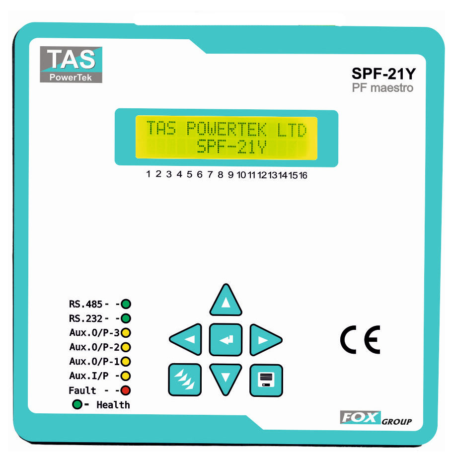
User-Friendly LCD Display and Soft-Touch Keypad Interface
Provides easy access to real-time data, configuration settings, and historical event logs via atwo-line backlit LCD and intuitive 7-key navigation.
Firmware Upgradability via RS-232 Interface
Allows future functionality enhancements, compliance adaptations, and security patches without requiring controller replacement, protecting long-term investments.
Rugged IP54 Fire-Retardant Housing with Full Compliance
Engineered with fire-retardant ABS material, IP54 front protection, and compliance with IEC 61326-1 EMC, CE, and RoHS3 standards, ensuring reliable and safe operation in harsh industrial conditions.
Technical Specifications
| Function | Parameter | Condition | Minimum | Maximum |
|---|---|---|---|---|
| Measurement | ||||
| Supply | Voltage (V) Sinusoidal |
3-Phase & Neutral - fundamental 3-Phase (3-wire) - fundamental 2-Phase - fundamental 1-Phase & Neutral - fundamental |
50V~ L-N 85V~ L-L 85V~ L-L 50V~ L-N |
315V~ L-N 550V~ L-L 550V~ L-L 315V~ L-N |
| Current (I) Sinusoidal |
5 Amp IN: - fund. 1 Amp IN: - fund. |
75mA(cl-2), 5mA-min 200mA(cl-2), 5mA-min |
7.5 Amp 1.5 Amp |
|
| Frequency | Frequency (Hz) (Fundamental Supply Voltage measurement of frequency) |
47Hz (for 50Hz) 57Hz (for 60Hz) meas range 45Hz |
53Hz (for 50Hz) 63Hz (for 60Hz) meas range 65Hz |
|
| Power / Energy | IEC-62053 pt.21 & 23 4 quadrant measurement |
5Amp range: Class 2: P & Q 1Amp range ≥200mA: Class 2 P & Q |
||
| Maximum Demand | S (VA) 1 min sliding window P (W) Window time user set |
Window time 5 - Minutes |
Window time 60 - Minutes |
|
| Harmonics | Voltage - L-L & L-N Current - per L (RYB) & N |
Spectrum: 2nd to 31st Harmonic. For Voltage and Current. |
||
| VA Burden | Voltage at 550V~ L-L Voltage at 415V~ L-L Current at 7.5Amp~ S-CT Current at 5.0Amp~ S-CT Current at 1.0Amp~ S-CT |
<1.13VA per ph., <3.40VA total 3-ph <0.65VA per ph., <1.95VA total 3-ph <1.0VA per ph., <3.0VA total 3-ph <0.5VA per ph., <1.5VA total 3-ph <0.05VA per ph., <0.15VA total 3-ph |
||
| Capacitor | Current |
5 Amp IN: 1 Amp IN: |
75mA(cl-2),25mA<0 15mA(cl-2),05mA<0 |
7.5 Amp 1.5 Amp |
| Harmonics | Cap. Current - per Ph | 2nd to 31st Harmonic | ||
| VA Burden | Current at 5.0Amp~ C-CT Current at 1.0Amp~ C-CT |
<0.5VA per ph., <1.5VA total 3-ph <0.05VA per ph., <0.15VA total 3-ph |
||
| Bank VAR value |
Fund. Voltage, Cap. Ampare & frequency normalized value. |
% of capacitor current CT rating. Accuracy 3%: 10% to 150% C-CT rated Accuracy 10%: 2% to 10% C-CT rated |
||
| Capacitor Control | ||||
|---|---|---|---|---|
| PF Correction | Target PF | Displacement Power Factor setting | Inductive: 0.000 | Capacitive: 0.000 |
| VAR margin | Smallest capacitor bank VAR … X | … X 1.1 | … X 9.9 | |
| Offset to target | % above the target PF setting | 0% | 100% | |
| ON/OFF control | Algorithm | Optimal value to target. | Single target PF with adjustable No action VAR tolerance band | |
| Bank Utilization | Limit = (Number of switch ON / C) + (On duration in Minutes / T) |
C = 01(00 for Disb.) T = 01(00 for Disb.) |
C = 99 T = 99 |
|
| High Speed Pull-up Solid State switching |
Group of 5 numbers (3-groups) + Transistor switched high speed on/off |
Voltage: +10Vdc Amp: 0mA dc |
Voltage: +24Vdc Amp: 30mA dc (<2.5V drop) Current limit: 32–40mA |
|